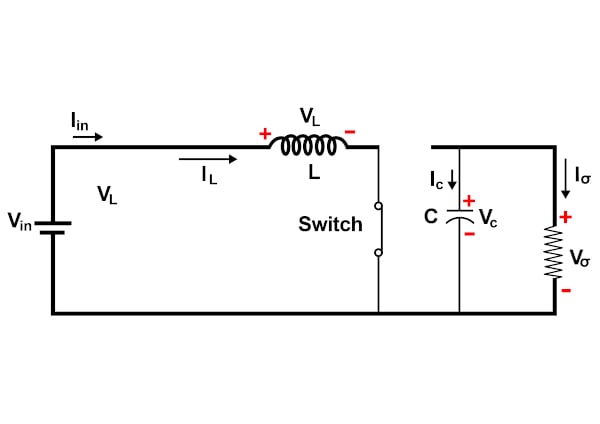
Schematic diagram of a basic Step-Up converter integrated in a
Von einem Mystery-Man-Autor
Last updated 19 mai 2024

Download scientific diagram | Schematic diagram of a basic Step-Up converter integrated in a photovoltaic generator. PV is a photovoltaic panel, PWM is the Pulse Width Modulator. C1, C2, Rp, Rs, L1, D1 and M1 are the discrete elements constituting the electronic circuit (see the text). from publication: Basic MOSFET Based vs Couple-coils Boost Converters for Photovoltaic Generators | Considering the optimization of a photovoltaic system, several studies show the advantage in the choice of a distributed structure. For such structures small power converters such as the boosts and buck converters appear as most appropriate. We have analysed the efficiency of | MOSFET, Photovoltaics and Boost | ResearchGate, the professional network for scientists.
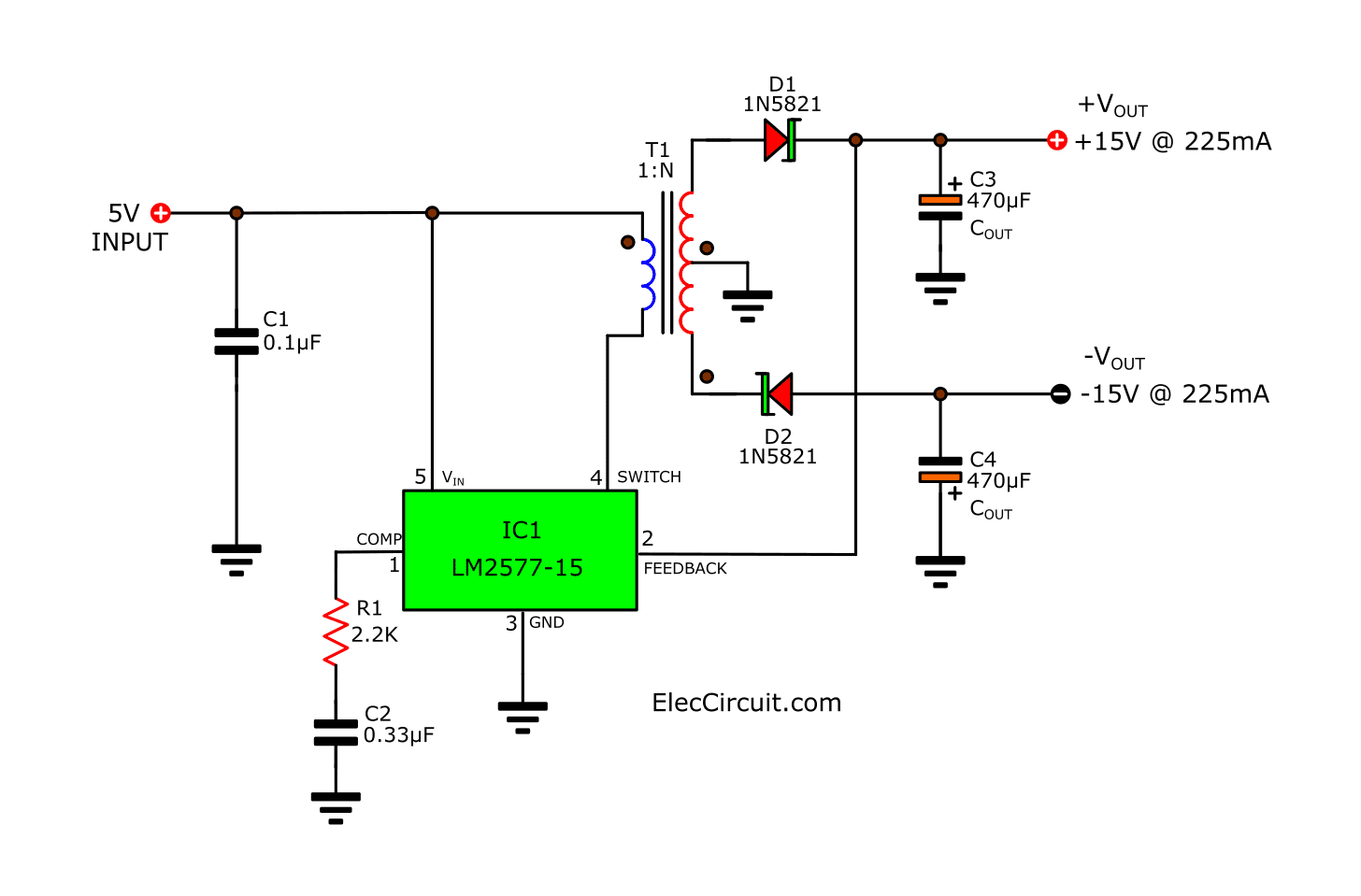
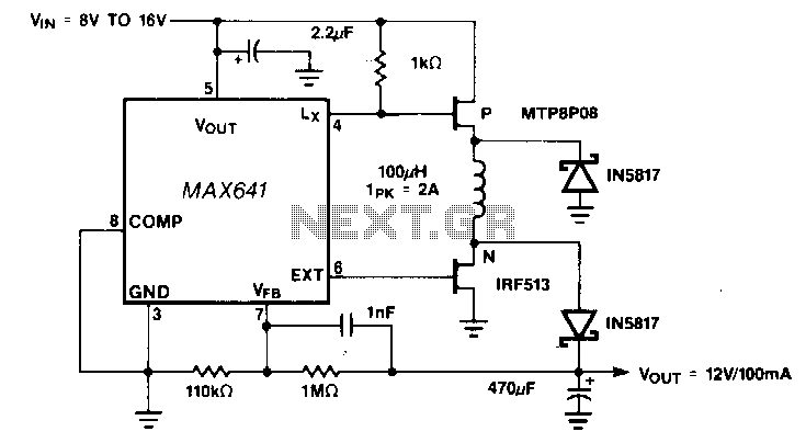
LM2577 Boost Converter circuit, Step up, Datasheet

Step-up Booster : 4 Steps - Instructables
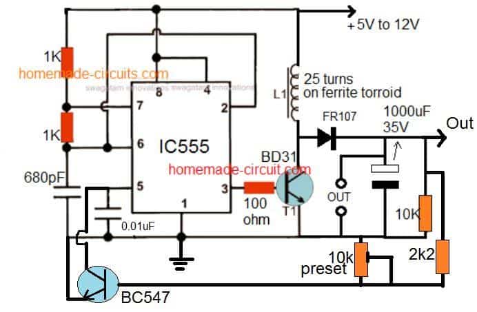
How to make a simple and powerful 3.7V to 12V boost converter

High Voltage Boost and Inverting Converters for Communications
4 Easy Boost Converter Circuits Explained - Homemade Circuit Projects
DC to DC Boost Converter Circuit (Part 5/9)

Non-isolated high step-up DC/DC converters – An overview
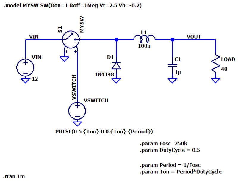
Understanding Switch-Mode Regulation: The Buck Converter
Step-up-down-dc-dc-converter under AC-DC & DC-DC Circuits -13223
für dich empfohlen
 DC/DC Converters: Devices for Converting to a Higher Voltage - Technical Articles14 Jul 2023
 Boost Converter, Step Up Chopper14 Jul 2023
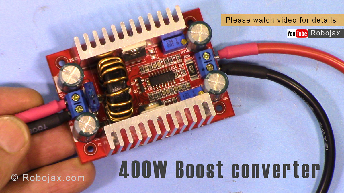 Review of 400W DC Step-up Boost Converter input 8.5V-50V to 10V-60V - Robojax14 Jul 2023
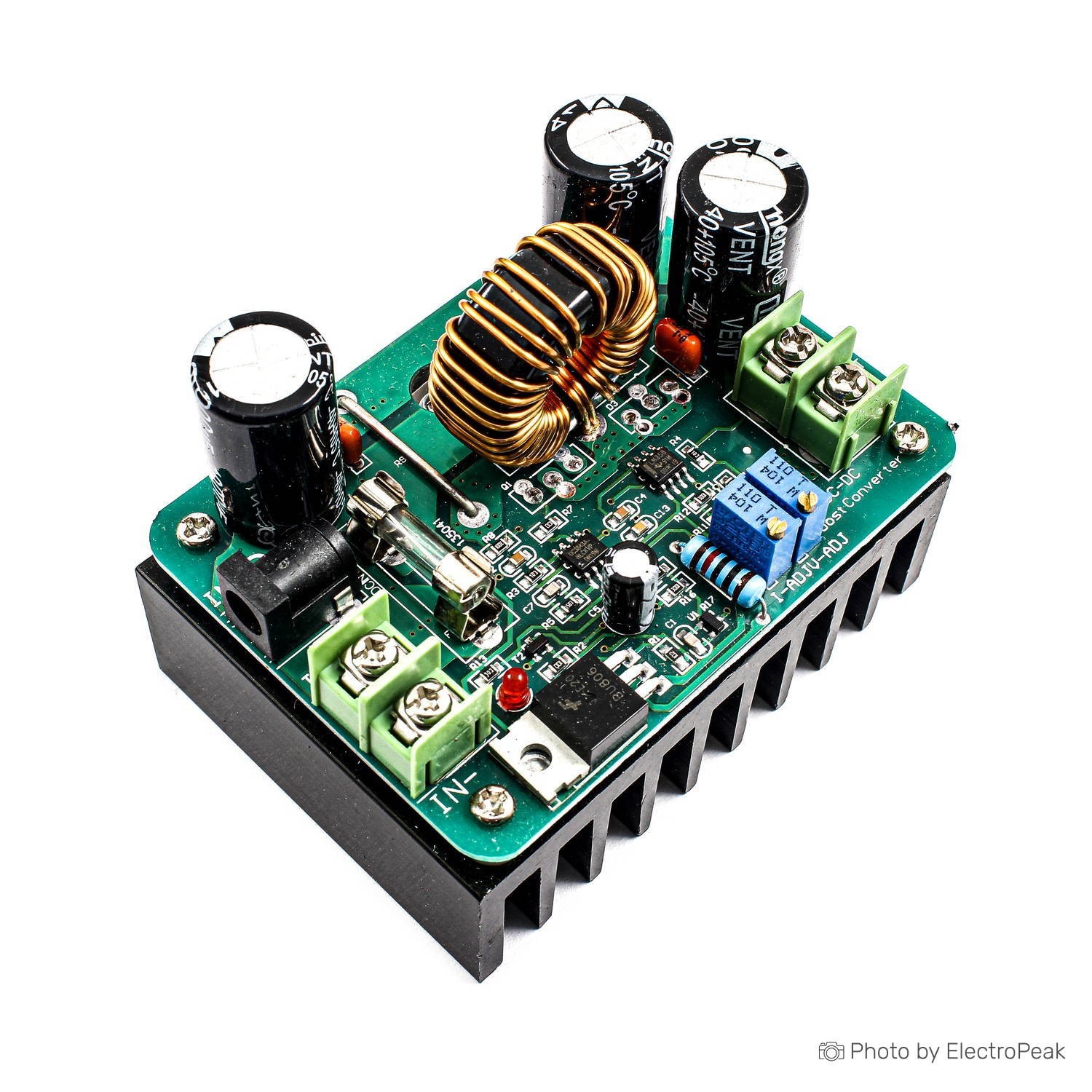 10A 600W DC-DC Adjustable Boost Converter Step Up Voltage Regulator Module14 Jul 2023
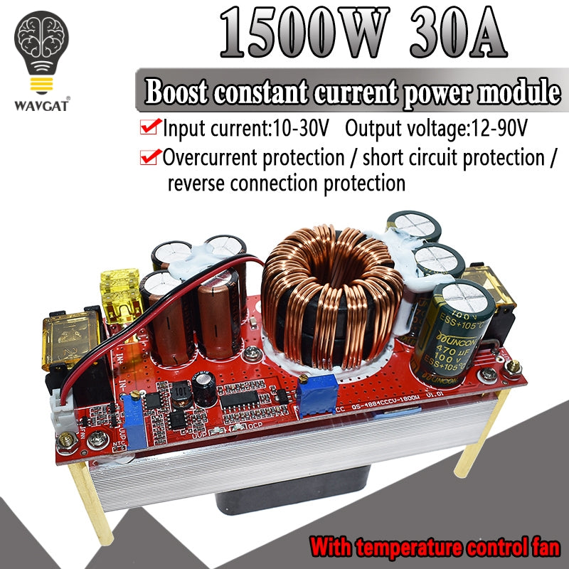 DC-DC 1500W 30A Voltage Step Up Converter Boost CC CV Power Supply Mo – TODOELEC E&E Market14 Jul 2023
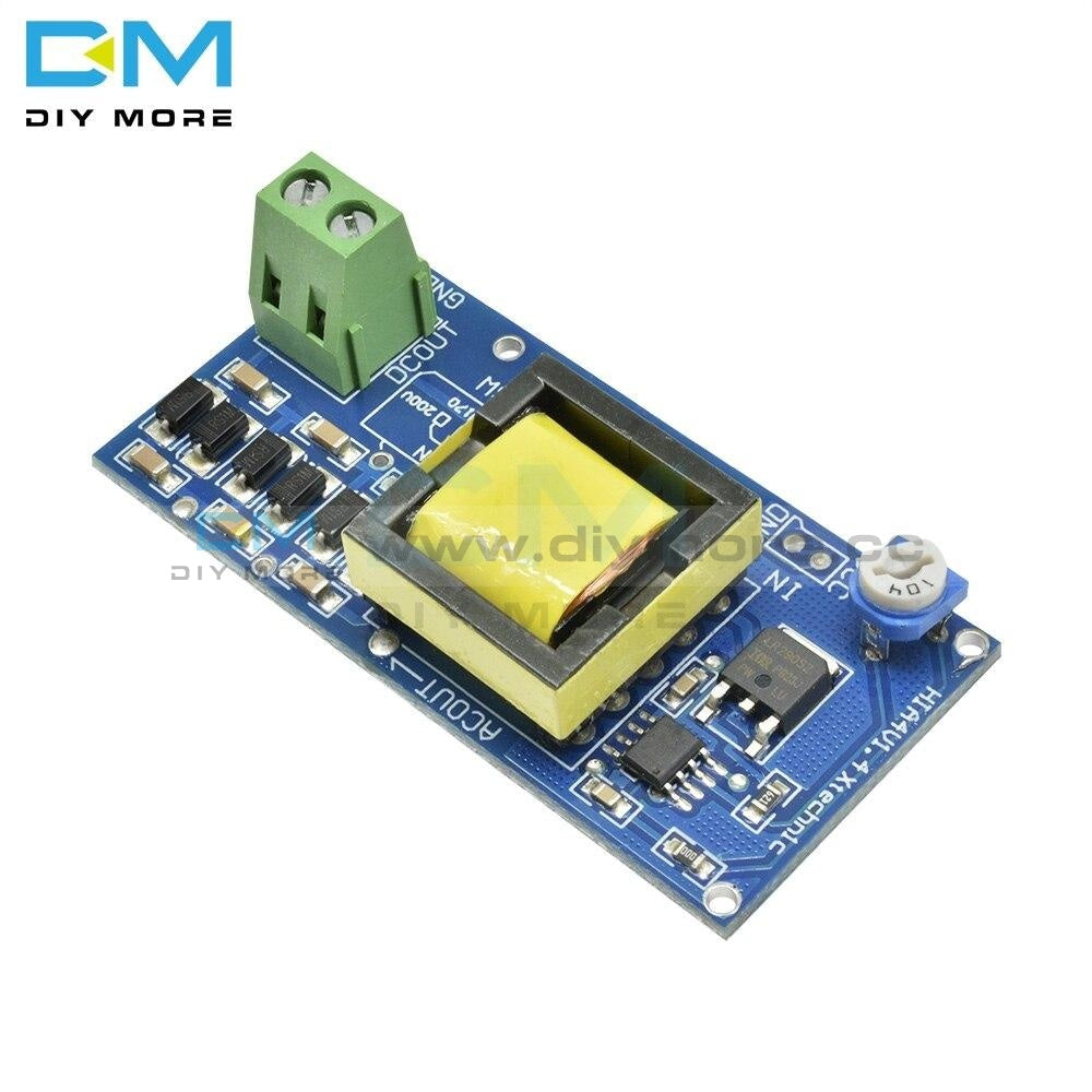 DC-DC High Voltage Boost Converter Input 3V-5V Output 1000V Power Supp – diymore14 Jul 2023
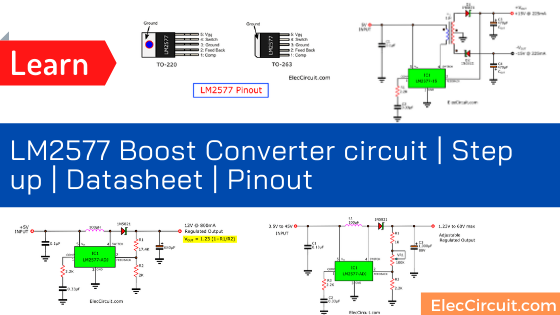 LM2577 Boost Converter circuit, Step up, Datasheet14 Jul 2023
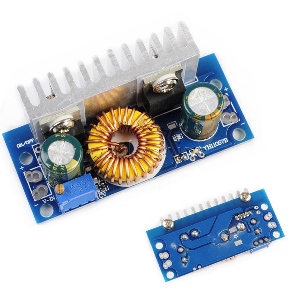 Boost Step-Up 4.5-32V to 5-42V 5A Adjustable DC-DC Converter14 Jul 2023
 5pcs Dc Dc 1.8v 2.5v 3v 3.3v 3.7v To 5v Step Up Power Supply14 Jul 2023
 10pcs Dc-dc Boost Converter Step Up Module Board 1v-5v To 5v 500ma 600ma Max For Arduino High Efficiency Frequency Quality - Integrated Circuits - AliExpress14 Jul 2023
Sie können auch mögen
 5KW 12V 24V car Diesel Air Heater Vehicle Heater Set 4 Holes14 Jul 2023
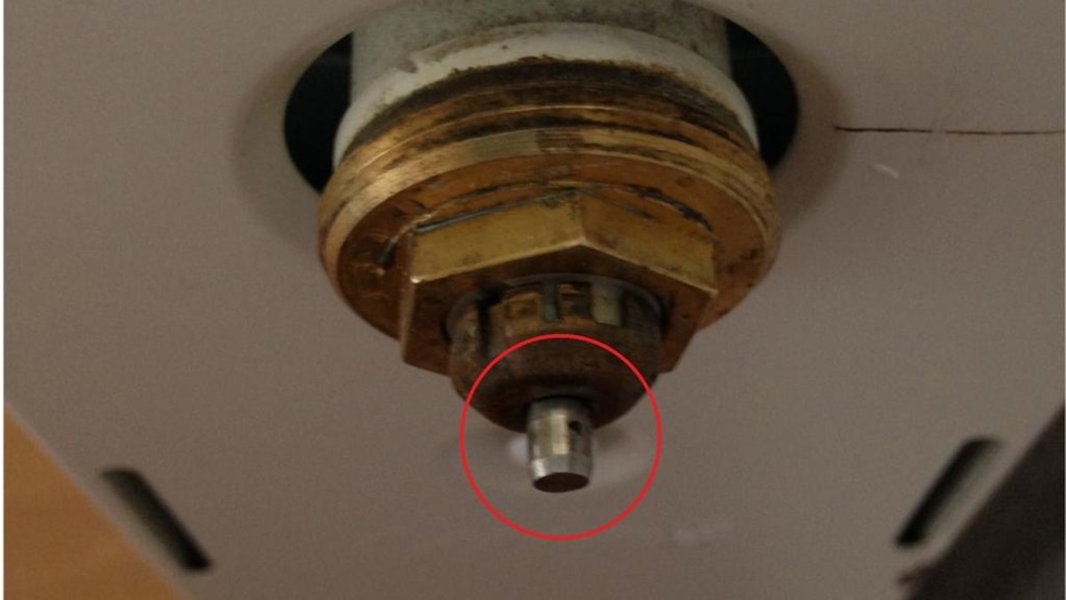 Heizungsventil klemmt - das können Sie tun14 Jul 2023
 Audi a6 c5 20 Getunte autos, Autos, Klassiker14 Jul 2023
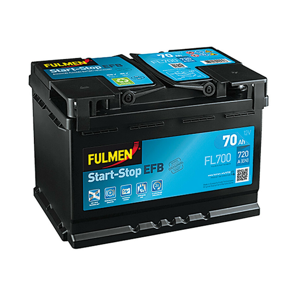 Batterie 12V - Fulmen Start-Stop EFB - 70 Ah - 720 A - L0314 Jul 2023
 50cm Halskette + Afghanistan Anhänger in massiv 925 Silber14 Jul 2023
 GPS Volkswagen Golf 4 MK4 (1997-2003): Wholesale price14 Jul 2023
 BMW logo doesn't actually depict a propeller14 Jul 2023
 Silikonkühlerschlauch Silikonschlauch Kühlwasser Kühler Heißwasserschlauch14 Jul 2023
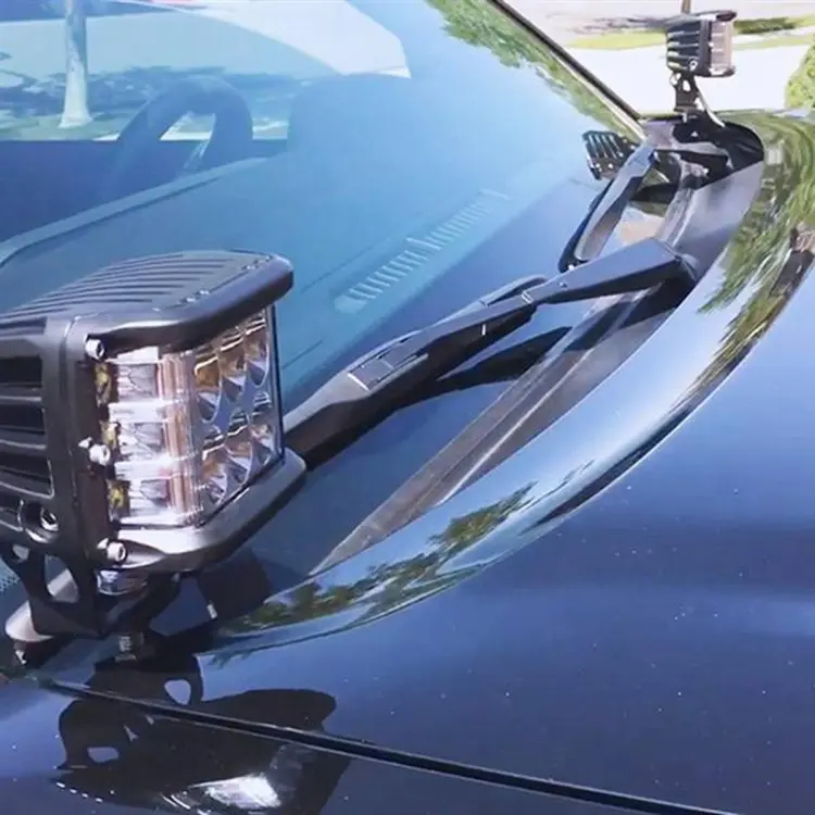 LED Light Pod Metal Hood Mount Bracket Ditch Hood Light Brackets Accessory Kit for 2016-2020 Toyota Tacoma14 Jul 2023
 INNEN TÜRGRIFF ABDECKUNG Set für Mini Cooper Countryman R60 Union14 Jul 2023